The fundamental principle of laser cutting relies on high-energy beams to melt or vaporize materials, with processing quality being closely tied to power density (power/velocity).
However, during actual cutting operations, particularly at corners, cutting head speed drops dramatically, causing energy buildup. This explains why corners often suffer from burn-through, burrs, slag buildup, or failure to cut through.
The Essence of Corner Cutting Problem: Speed and Power Game
We know:
Power = Energy output by the laser per unit time (W)
Speed = Distance the cutting head moves per unit time (mm/s)
The cutting head maintains constant speed with optimal power matching during straight-line cutting, delivering excellent performance. However, when approaching corners:
- Reduction is unavoidable: To ensure precise steering of the cutting head, the control system must reduce acceleration (to avoid mechanical vibration), resulting in a sharp deceleration at corners.
- Energy accumulation: When power is constant, low speed causes a sharp increase in energy absorbed per unit length (J/mm), which may lead to over-burning (burrs or slag adhesion). Conversely, insufficient power may result in cutting failure.
Solution: Dynamic Adjustment of Speed-Power Curve
The ideal laser cutting process should follow the dynamic matching principle of "increasing speed to increasing power, decreasing speed to decreasing power", and ensure the stability of corner energy density by adjusting power to compensate for speed change in real time.
Most laser cutting control systems provide the tool of speed-power curve to facilitate the user to match the relationship between the two.
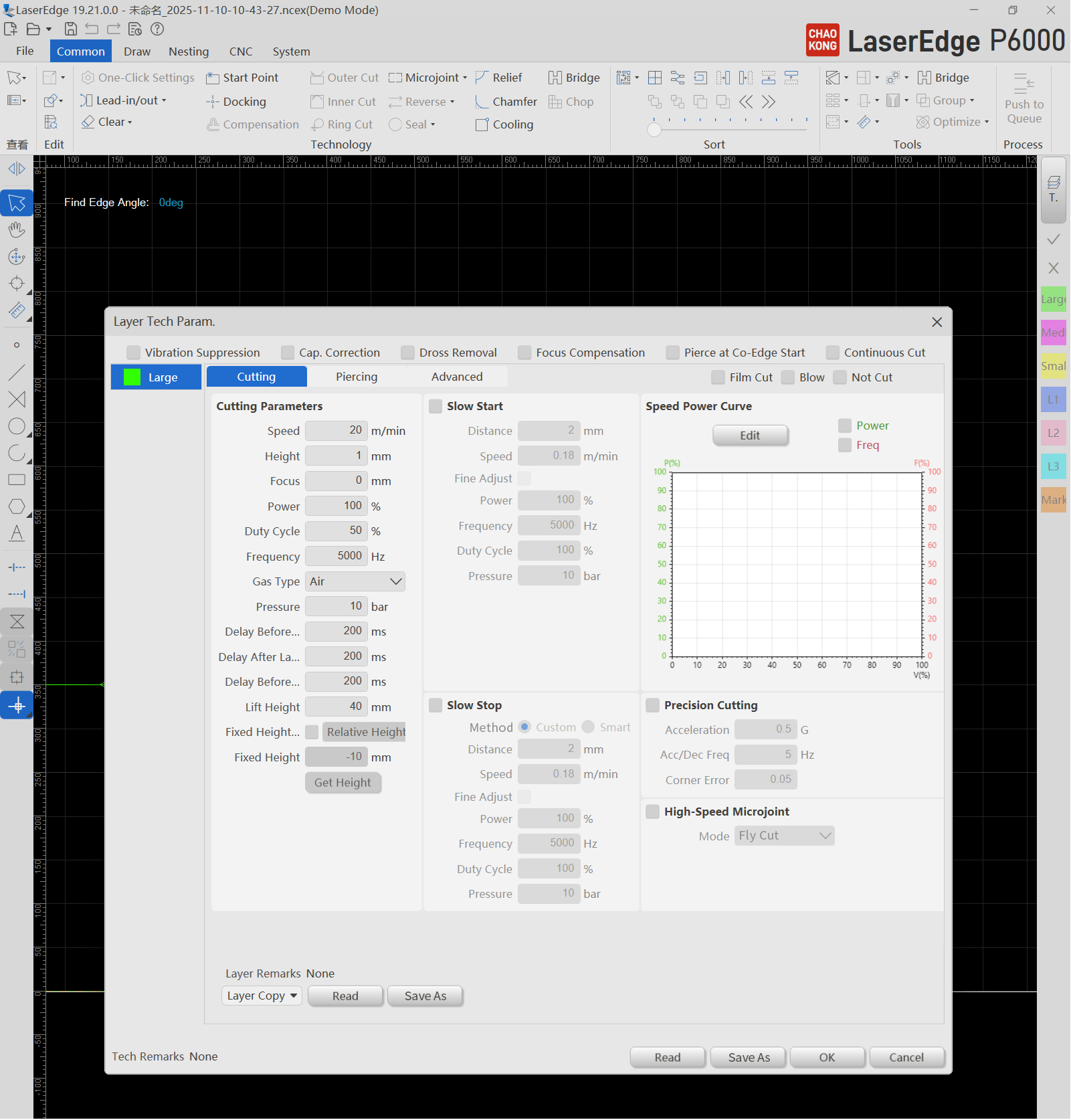
How to Set the Speed-Power Curve?
Basic Settings (for most materials):
When speed is 0% (e.g., during perforation): Set power to 30% to prevent burnout at the start.
When the speed is 100% (full-speed cutting): Set the power to 100% (peak efficiency).
Corner optimization:
If burrs appear at the corner: this indicates excessive power or energy at low speeds causing overheating. Reduce power in the low-speed range (for example, decrease power from 70% to 50% when the speed is 30%).
If the corner cannot be cut through, this indicates insufficient power or energy at low speeds. Increase the power in the low-speed range (for example, raise the power from 50% to 65% when the speed is 30%).
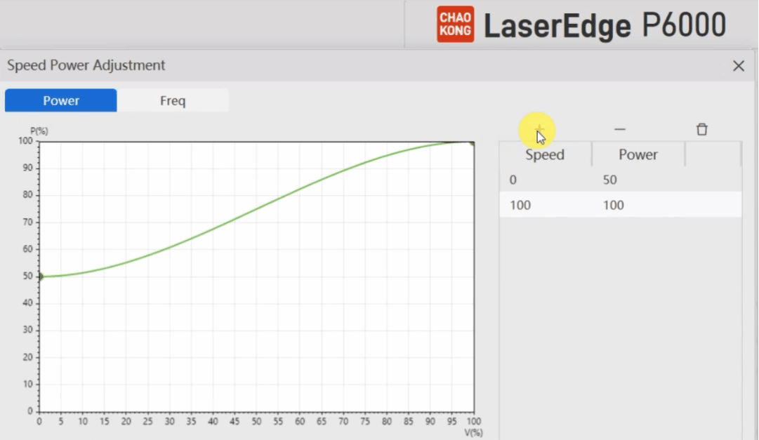
Operation Demonstration (Mainstream Laser Cutting Systems as Example)
Drag adjustment: Drag curve nodes to observe corner effects in real time.
Add or delete nodes: Double-click the curve to add or remove key control points for fine adjustment.
Smooth transition: Enable "Smooth Mode" to prevent uneven heat-affected zones caused by power surges
Advanced Technique: How to Verify the Curve Effect?
Analysis by high-speed camera: Observation of the direction of slag spray at the corner (ideally, it should be vertical downward).
Metallographic inspection: Check the thickness of slag on the cross-section (preferably <50µm)
Pilot production: Cutting quality and consumables life under different speed-power mixture
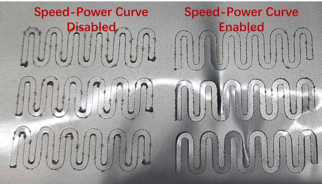
Conclusion: Delicate Tuning for High Quality Cutting
The core challenge of laser cutting corners is essentially an art of balancing energy control.
By strategically configuring the speed-power curve, users can:
- Reduce burrs and slagging (when energy is excessive)
- Avoid incomplete incision (insufficient energy)
- Extending lens/nozzle life (under stable thermal load)